One of the requirements for our network and demonstration is to implement a VPN connection between the Christchurch and Nelson branches.
This will enable the two separate LANs to communicate with eachother through a separate VPN connection. This connection is secure, and encrypts data in transit.
Our network in TALOS currently has 3 ‘virtual switches’ (it’s easier to call them switches to avoid confusion). which we use in conjunction with pfSense routers (1 in each LAN) to separate the networks.
We are using GA-1 for Nelson, GA-2 for CHCH, and GA-3 for our ‘WAN’ or ‘internet’ network.
The WAN currently only uses 2 IPv4 addresses, these being the WAN interface of the pfSense routers. Christchurch: 10.10.3.1 | Nelson: 10.10.3.2.
The Chch ‘WAN pfSense’(10.10.3.1) connects GA-3(WAN switch) to GA-2(CHCH switch). LAN: 192.168.1.0/24
Nelson pfSense WAN (10.10.3.2) connects GA-3(WAN) to GA-1(NSN)
LAN: 192.168.2.0/24.

Example of how pfSense bridges WAN to LAN (I have drawn it as 2 routers, 1 WAN and 1 LAN as this is easier to understand, different rules are set and they act as different networks. In reality, it is 1 pfSense VM, and 1 virtual switch for each branch).
These networks are on different subnets, therefor they cannot communicate between the 2 LAN networks, the devices would be unreachable as the routers don’t know about each others LAN devices.
To fix this, we use a Virtual Private Network. In this case, a peer-to-peer VPN. The VPN uses a separate, new network, made purely for the purposes of this mapping/connecting the devices.
We will use OpenVPN, it is built into pfSense, and provides a lot of options. Christchurch pfSense will act as the OpenVPN server, and Nelson will connect as the Client.
Step by Step Guide:
Starting with the pfSense that will be the ‘Server’ for the VPN
- Open OpenVPN page

2. Click ‘Add’ under server tab

3. This brings up the setup screen. Change server mode to Peer to Peer (SSL or TLS can be used to use certificates or other authentication methods, but for simplicity, we will use peer to peer).
4. Change Protocol to UDP or as required.
5. Should be on the WAN interface, the default port used is 1194, if this port is not already in use, it is fine to use.

6. Set encryption algorithm, (Once server has been created, click edit on newly created server and a key will have been generated)
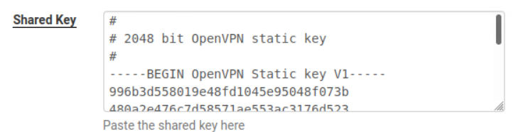
7. Copy shared key (this will be needed when setting up Nelson client).
8. Create the network for the VPN tunnel, this must not be a network that is already in use. (I have used 172.16.1.0).
The IPv4 chosen must also be a private non-routable address (e.g. class A,B,C) (e.g. 10.x.x.x/8, 172.16.x.x-172.31.x.x/12, 192.168.x.x/16).

9. Set the IPv4 Remote network. This will be the LAN that will be connecting to this network, in my case that’s Nelson branch, so the Nelson network has been entered (192.168.2.0/24).
10. Create the server (You can see an example of the created server in step 2 picture)
11. Go to Firewall rules, add rule to WAN to allow port 1194.
12. There will be a new firewall tab called OpenVPN, a pass all rule can be created in here. If no rule is created, the service wont work (You can create more rules to suit the needs of the VPN).


13. Click into the interfaces tab. There will be an option to ‘add’ a new OpenVPN interface. Click add.

14. Go into the new OpenVPN interface, enable interface, gives a description.

15. The IPv4 won’t show straight away, it will say n/a. The OpenVPN service just needs to be restarted, then the new VPN IP will come through like so.

16. Setting up the Nelson pfSense Client Side. Switch to Client/Nelson pfSense. Click into OpenVPN, change to Clients tab, click ‘add’ to create a new client profile.

17. Same as before, P2P, UDP, WAN, port 1194, but this time
18. Server host or address, this is the IP of the pfSense machine that we have just created the server on (Christchurch pfSense WAN IP).

19. Make sure that the encryption algorithm is exactly the same as the server side, uncheck ‘Automatically generate shared key’, and paste the server key that we copied earlier.

20. Set the same Tunnel IPv4 address, and this time the other LAN (that will be connecting to this side, e.g. the servers LAN) In my case this is CHCH’s LAN, 192.168.1.0/24

21. Create the client side OpenVPN. Add firewall rules like before.
22. If done correctly, the devices should now be able to ping eachother, despite being in different networks. Communication is mapped through the 172.16.1.0/24 OpenVPN network that we have set up.
23. Devices on CHCH LAN can now ping and communicate with devices on the Nelson LAN and vice-versa.
To check in full detail, I installed traceroute and mapped the route

This is from the Chch Ubuntu Client 192.168.1.3, it first hits the CHCH router 192.168.1.1, which sends it through to the VPN network with an IPv4 of 172.16.1.2, and out the other side in Nelson at 192.168.2.3 (NSN Ubuntu Client).
Issues Encountered
After setting up all the firewall rules, the WAN connection was still getting blocked, stopping the service from functioning. The cause of this was due to a built in rule by pfSense. Under WAN, find this rule

This part of the rule was causing the Firewall to block access due to the IP I chose being a 172.16 number.